The Long EZ
Wing Page 2
Home
LONG EZ BACKGROUND
FUSELAGE
THE PANEL
CANOPY
STRAKES
LANDING GEAR
THE CENTER SECTION SPAR
WINGS
CANARD
ENGINE
LINKS
SWAG SECTION

BUILDING THE WINGS

The first step in actually building the wings is to lay out the wing spar.  They are leveled on sawhorses and five gallon buckets.  The spars are then sanded.  Slurry is then added to the forward space of the spar and the cores are bonded to the leading edge. 


Tape and screws are then added to hold the cores in place until cure.  At this point my friend Phil (quality control) stated that if I did not go ahead and drill the 1/4 pilot holes in the spar   into   5/8 holes, I would not be able to reach them once I added the rear cores.  So $23.00 later I had a 5/8 drill bit that went through the aluminum like a hot knife through butter.  I then opened up the pilot holes  to 5/8.


The next day the spars are flipped over and the rear cores are added and then taped and screwed into place.  They are then left to cure.   The spars  are now ready to be laid flat and layed up in triax.  The hole  just visible in the leading edge core is the conduit for the rudder cable and the nav light/strobe wiring.


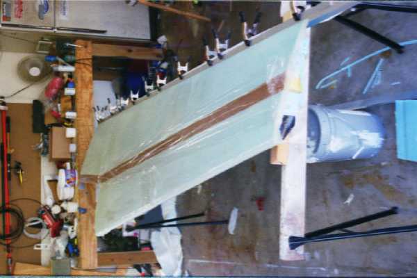
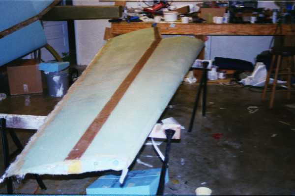
At right is a picture of the first layup on the underside of the wing.  The wrinkling you see is saran wrap placed over the spar to avoid air seeping into the layup as it cures.  The aluminum I-beam is under the trailing edge.  Aluminum yardsticks were then clamped down on top of the I-beam with the glass in between.   That makes a straight flat trailing edge.


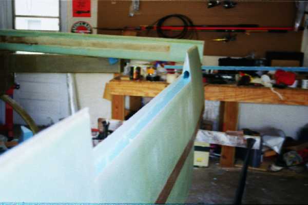
In this picture the wing  has been flipped over and  the top layup of triax is in place.  Notice the trailing edge has a glass to glass bond of about two inches.  This will be timmed with a dremel tool after cure.


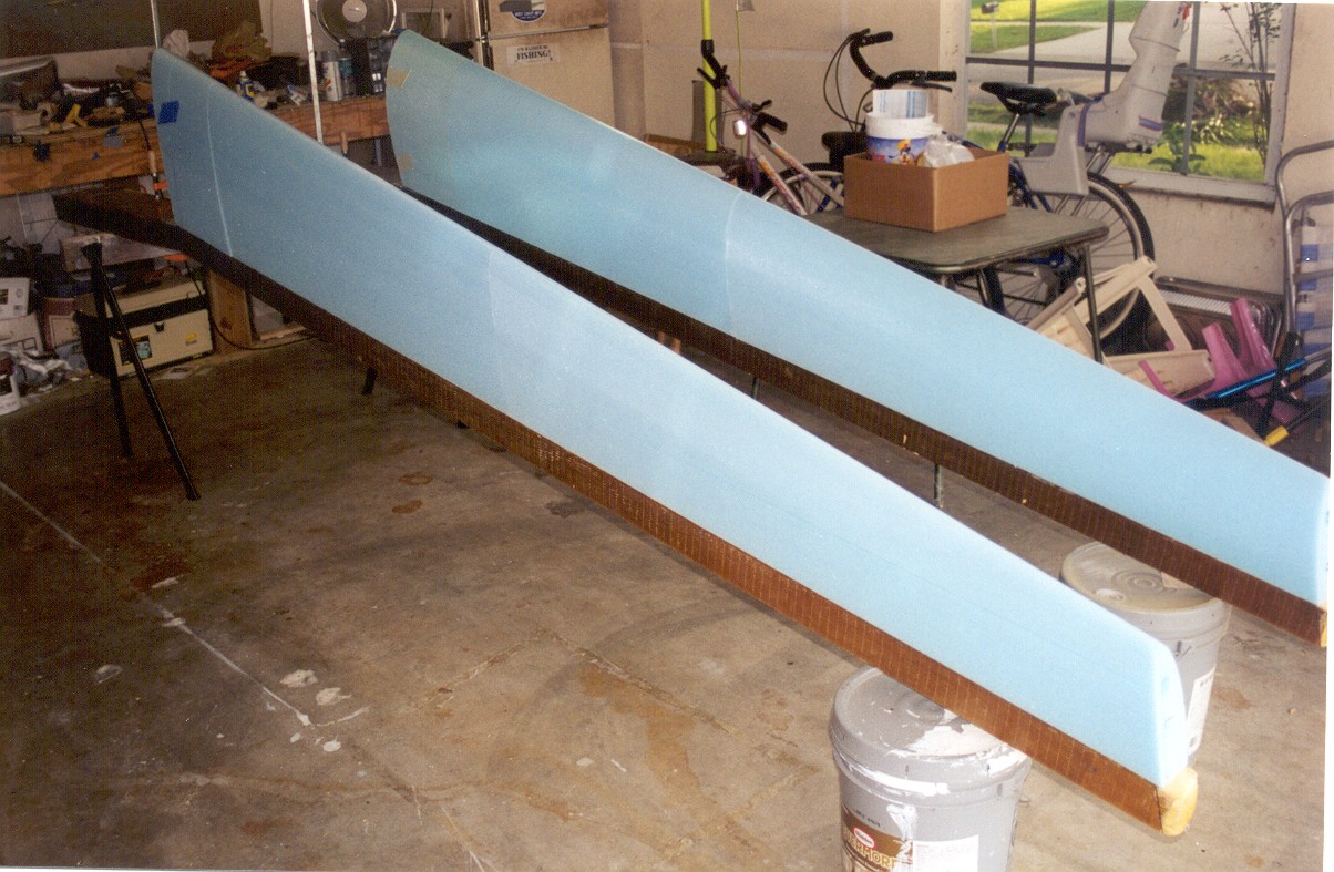
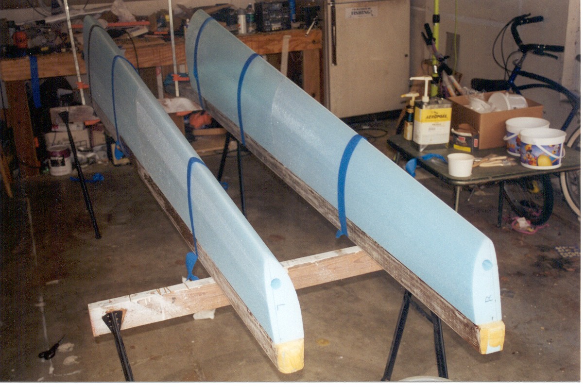
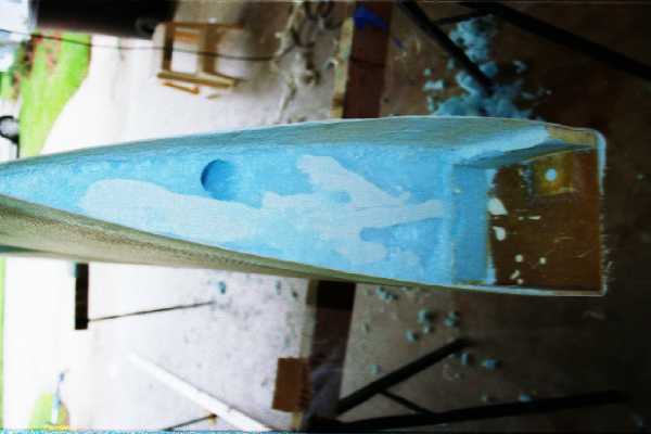
The wing has been cured and trimmed around the edges.  The cores come with the aileron cutout pre-marked. A dremel tool and saw is used to cut out the aileron.  The foam is then removed in the wing to provide a U-shaped channel for the aileron movement.  The hole visible in the inboard section is for the aileron torque tube.


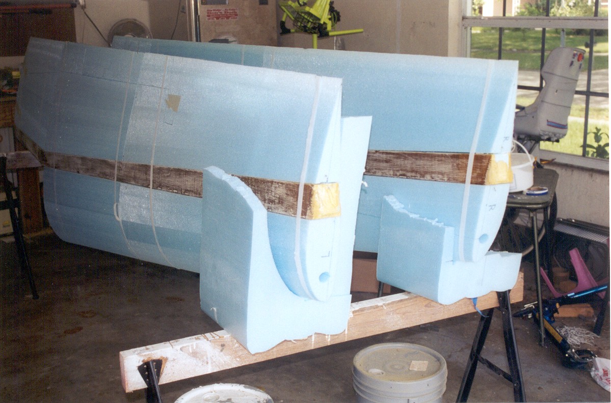
Foam is then cleaned out of the root section.  The hole for the aileron torque tube is visible here also.  This section will be glassed over the aileron pushrod and bearing will be added in this space.

wing1.jpg

wing3.jpg

wing2.jpg

24_24.jpg

23_23.jpg

06_06.jpg

05_05.jpg

Wing page 3