The Long EZ
Engine page 3

HOME

LONG EZ BACKGROUND
FUSELAGE
THE PANEL
CANOPY
STRAKES
LANDING GEAR
THE CENTER SECTION SPAR
THE ENGINE
WINGS
CANARD
LINKS
THINGS I'LL DO DIFFERENT NEXT TIME

engrearv.jpg

Here is a picture from the rear of the engine after it has been attached  to the plate.  The mount has also been painted with hi temp auto engine block paint.  The manual transmission flywheel has been removed.  I ordered an auto trannny flywheel and counter weight from Mazda Mart in Atlanta.  The needle bearing inside the end of the eccentric shaft also must be removed.  Another modification recommended by Tracy was to remove the eighteen tension bolts, those are the bolts you see in a rough circle around the shaft. The bolts were removed one at a time and a strip of Permatex Ultra Grey was applied, the bolts were then resintalled.  The silicone cuts down on the vibration of the bolt.

damper.jpg

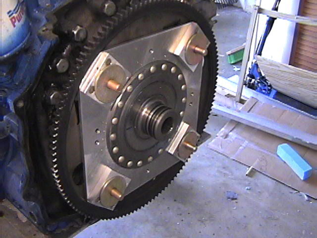
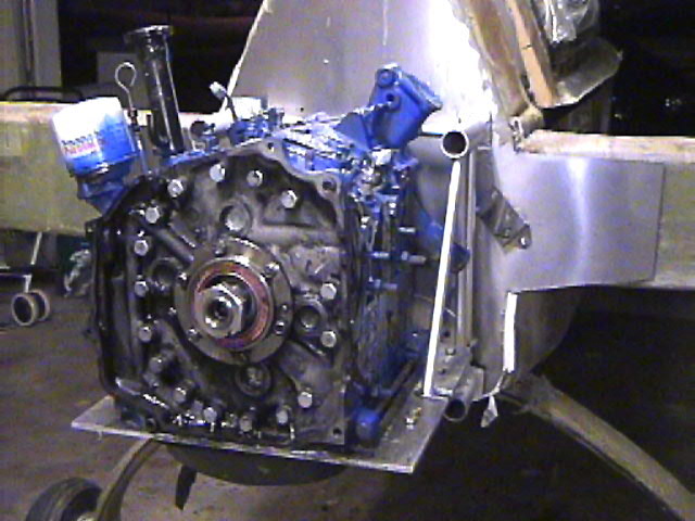
Here the damper plate has been added to the flywheel, actually called a driveplate by Mazda.  This required removing a needle bearing inside the crank on my maunal version of the motor.

rdleft.jpg

rd1a.jpg

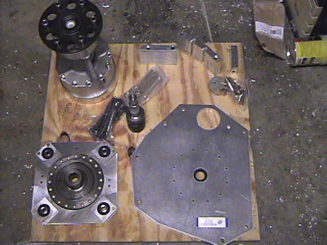
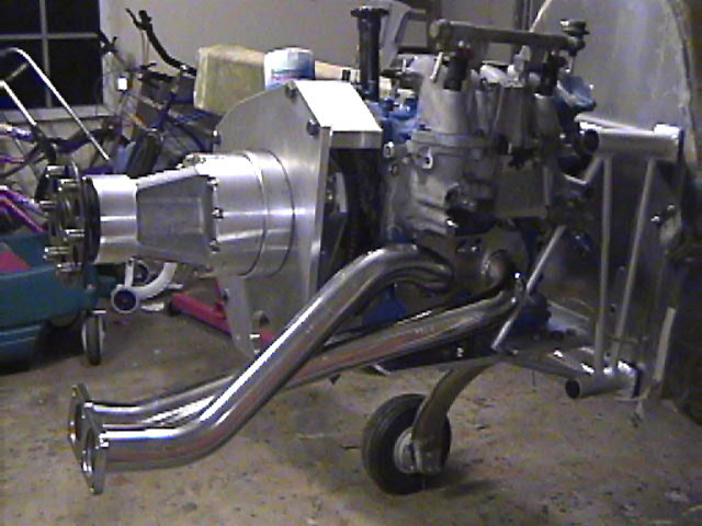
Above are all the parts of the RWS RD-1A redrive reduction unit. These parts will serve to convert rotary motion to forward thrust.  Hopefully, about 180 HP's worth.

rightvie.jpg

This is the left view of the redrive.  The adapter plate is bolted to the block.  The input shaft is added through the adapter plate and through the damper into the crank.  The planetary gear unit is then bolted on to the adapter plate.

This is the right side of the motor.  The stainless steel exhaust header will get cut down to size.  You can see the stock intake manifold with the injectors and fuel rails installed.  This might or might not be the final fuel delivery system.

Enter supporting content here