|
|  |
|
A rotary design is going to cause me to "engineer" my own fuel, ignition and other systems. The first of these was the motor mount. Going to various web sites, I was able to get a rough idea of what I wanted. I sat down and designed my own full size templates on posterboard . Then I ran the math and found that with a 300 pound engine and systems weight the mount would be good to about 6 G's. That actually is conservative because I think my weight will be less than 300 pounds. Then I ran my numbers past an engineer friend and he agreed. My engineer friend is also a welder and welded up the mount. The main difference is the lower mounting point of the mount was moved to the bottom of the lower longeron rather than the middle longeron as in the plans. This was done to ease the stress on the lower diagonal in the mount. A company is making rotary mounts for several designs. I have heard good reports about them so far. They can be reached at http://www.conversionconcepts.com/
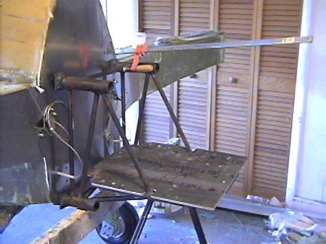
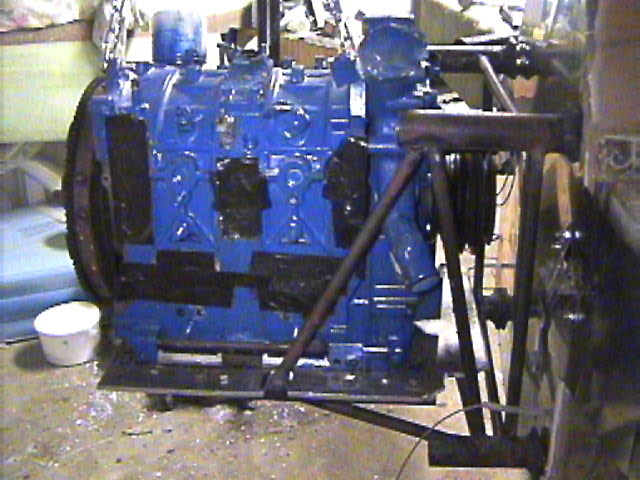
Above you see the first trial fitting of the MK-1, as it is known. It is slightly out of square, however, that can be cured with shims. Final weight is just under 15 pounds. Many thanks to Otto and Kurt Prochaska of Gulf Breeze, Florida for their input, opinons and most of all, Otto's welding.
|
|
|
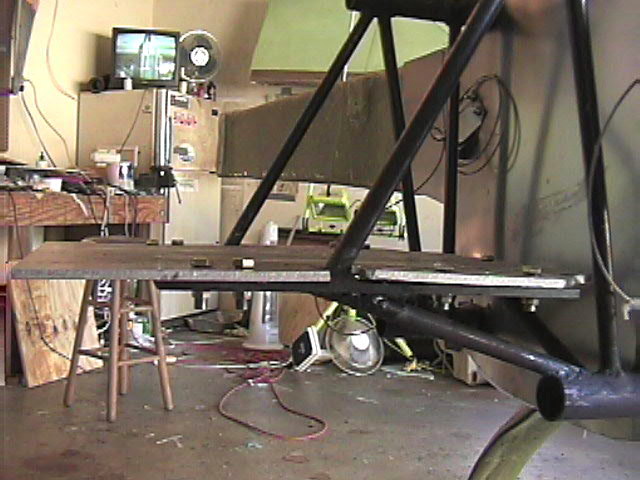
Before mounting the beast to the firewall, I made sure the plate was aligned properly and bolted to the mounting plates. The engine will sit centered on this plate.
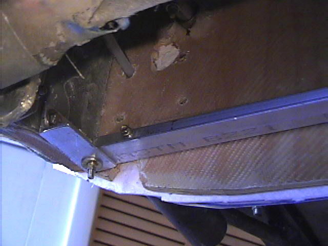
My mount attaches to the lower longerons instead of the lower part of the spar as in the plans. So I fabricated an aluminum angle support that is bolted between the lower longerons, the lower mounting bolts will attach to the vertical portion of this angle. All the stress is pushing forward, so the horizontal portion of the angle takes the load. This will also probably serve as the forward mounting point of my radiator.
Engine page 3 |
|
|
| |
|
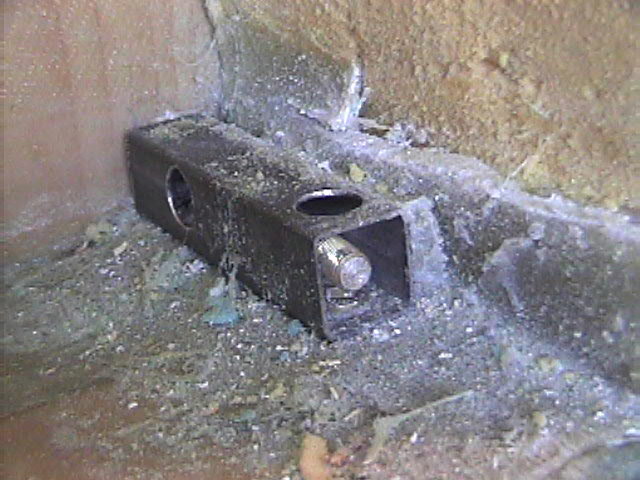
I made a slight change to the upper mount system from the plans. The plans have angle aluminum (or steel) which protrudes through the firewall. The mount is then held by bolts from the mount to the angle, the stress being held in "shear". I made my mount to sit flat against the firewall, then a AN bolt goes through the mount, through the firewall, down a 4130 steel "tube" and then is held by a bolt and 4130 washer on the end. Here you see the bolt just coming through the tube. This way the load on the bolt is in tension rather than shear. The tube is of course bolted to the spar and longerons.
Using the oil pan as a guide, I drilled the holes in the plate. Then I trial fit the engine onto the plate. I was happy, although not surprised, to see the holes line up. The engine block was placed on the plate and a few bolts were put in place. The clearance for such items as the manifolds and alternator looks better than planned.
|
|
|
|
|
|
|
| |