|
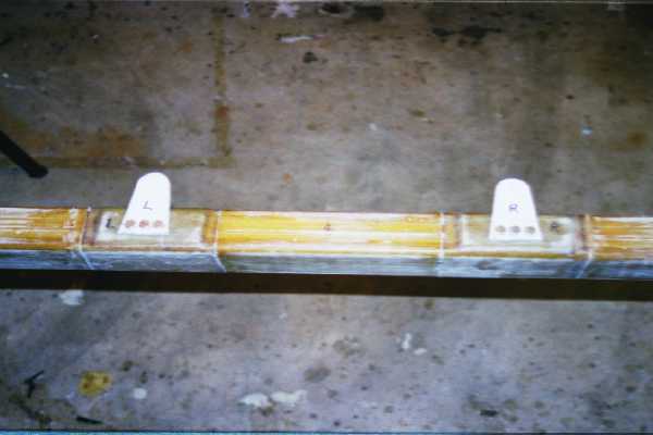
The pre molded spar from Aerocad is laid out between two sawhorses. The face is sanded. The lift tabs are
then installed. Jeff Russell at Aerocad had predrilled the tabs to match the nut inserts.
The front cores are in place when you bond the rear cores. I placed a board between the horses and put screws through
the lift tabs to hold the spar in place for the rear cores to cure.
|
 |
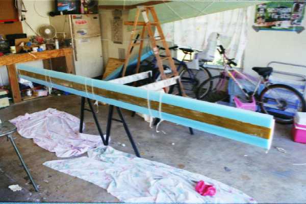
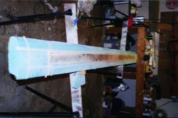
The foam cores are added to the forward and rear face of the spar. There are four cores on each face.
A void is sanded for the cores to fit over the lift tabs. After dealing with the wing core spars, these are
a piece of cake.
The canard contains two end core sections that attach to the end of the spar. The trailing edge I-beam from
the wing construction was used to make sure the core is aligned with the spar.
|
|
|
|
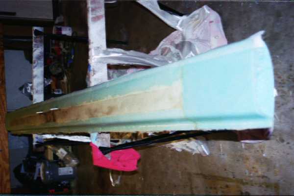
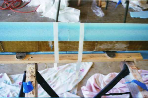
The plans say the lower canard face gets one layer UNI, one layer BID, then one more UNI layer. Slices are made
in the glass for the lift tabs to slip through. The white substance is slurry which was applied, allowed to cure and
then sanded to get a smooth transition from the cores to the spar.
The spar is then flipped over and tape is laid for the slurry coat to be applied to the foam just prior to the glass
layups. You can see there is slurry that has cured and been sanded to fill voids and make sure the upper surface is
smooth.
|
|
|
|
|
|
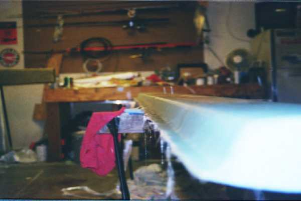
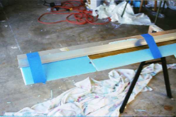
This is a close up of the trailing edge of the canard, looking at the underside. After cure, a one half inch section
of foam is removed along the trailing edge. It is then floxed before the upper layers of glass are laid in place.
That way you are left with a glass to glass bond for the trailing edge.
|
|